A flange guard can fit around a connection and still be difficult to install or remove. The body may clear the flange, but a side panel can touch a projecting stud, a latch can face a pipe support, or the hinged section can meet a wall before it opens far enough.
To size stainless steel flange guards, record the assembled flange dimensions, the profile passing through each side-panel opening, and the space needed to position, close, open and remove the cover. Nominal pipe size is a starting point, not a complete guard specification.
BSTFLEX Stainless Steel Flange Guards use a metal housing with annular side panels, a hinged opening and a latch closure. The following measurement checklist is intended for quotation and drawing review; final manufacturing dimensions and clearances require confirmation for the selected assembly.
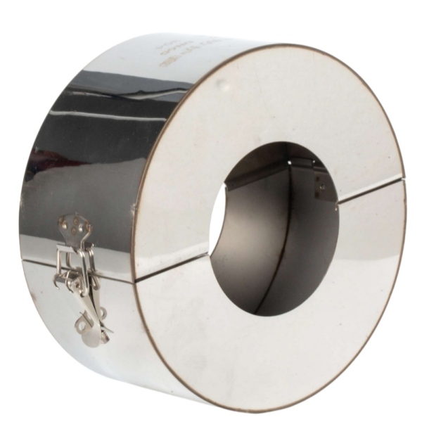
Identify the flange standard, nominal size, pressure designation and connection type before taking dimensions. Include the exact standard designation rather than describing the connection only as an American, European or Japanese flange.
BSTFLEX uses HG/T 20592 flange dimensions as one reference for sizing. Other flange standards can be reviewed against the relevant drawings and installed measurements. The flange pressure designation identifies the piping connection; it does not establish a pressure rating for the external guard.
Measure the connection in its assembled condition, with the actual nuts, washers and studs in place. Note any spacers, adapters or instrument connections between the flanges. Mark features that differ from the reference drawing instead of assuming that the standard flange dimensions describe the entire installation.
Use millimetres or inches consistently, and mark the measurement endpoints on a sketch. In particular, distinguish the width of the flange pair from the total space occupied by its fasteners.
| Measurement | What to Record | What It Helps Check |
|---|---|---|
| Flange outside diameter | The outside diameter of each flange. Record both when they differ. | The space needed inside the cylindrical guard body. |
| Assembled flange width | The axial distance between the outer backs of the two flanges, excluding projecting fasteners. Mark these reference surfaces on the sketch. | The basic width of the connection before checking nuts, studs and other projections. |
| Fastener projections | How far nuts, washers and stud ends project beyond each flange back. Include anything extending beyond the flange perimeter. | Possible interference with the side panels or outer shell. |
| Profile at each side-panel position | The pipe outside diameter and any hub, sleeve, coating or other feature at the proposed opening on each side. | The required opening shape and clearance at both ends of the guard. |
| Nearby obstructions | Distances to supports, walls, adjacent pipes, valve bodies, actuators and insulation that will remain in place. | Whether the closed cover and its hardware fit the available space. |
| Opening and removal space | The available access direction and restrictions around the hinge and latch. Include a wider installation photograph. | Whether the guard can be fitted and removed, not merely closed around the joint. |
These are connection measurements, not finished guard dimensions. Flange outside diameter is not the same as guard outside diameter, and measured assembly width should not automatically become the finished spacing between the side panels.
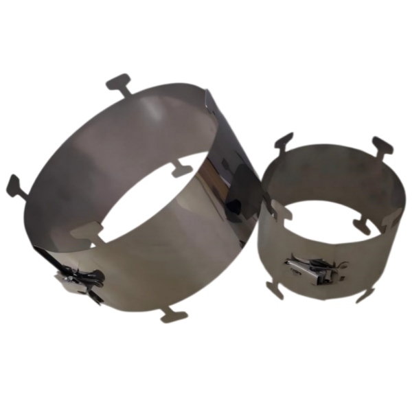
The annular side panels are the ring-shaped sections around the pipe openings. They extend inward from the outer housing, so their position must be checked against features that an open-sided band would not enclose.
Check each end separately. A straight pipe on one side and a valve body or flange hub on the other may present different profiles. Record the diameter at the proposed side-panel location, not simply at the nearest convenient section of exposed pipe.
Also identify where insulation or cladding stops. State whether it will remain outside the guard, pass through an opening, or be removed under the agreed installation plan. Do not leave that decision to the installer after the cover has been manufactured.
For an open-sided alternative, compare the construction of stainless steel band-type flange guards. Side panels change the coverage geometry and the fit requirements; their presence alone does not demonstrate a higher level of spray protection or pressure-tight containment.
Review the maximum external outline of the proposed assembly, including the hinge and latch. A body diameter that fits between two pipes may still leave insufficient space for the closure hardware. Show the intended orientation relative to nearby equipment.
Check access for the operator's hand and the movement of the latch, as well as the path swept by the hinged section. A gap beside a closed cover is not necessarily enough room to open it. Where orientation is restricted, mark the proposed hinge side and latch side on the drawing.
Consider the route by which the open housing reaches the connection and is lifted away again. Include fixed supports, adjacent valves and any equipment that cannot be moved during routine maintenance. For a valve connection, review the handle or actuator movement separately from the guard's opening movement.
As a layout example, two otherwise identical flange assemblies may need different guard orientations when one is beside a wall. The connection dimensions can be identical while the practical opening space is not. This is why a close-up flange photograph should be accompanied by a wider view.
Submit the dimensions as measured rather than adding an unspecified allowance to every value. The supplier needs to know which figures describe the connection and which describe your requested finished cover.
For hot-service installations, record whether measurements were taken with the system cold and provide the operating conditions. Identify any expected movement that the project's engineer requires the guard design to accommodate. Material selection, fit, fabrication tolerances and installation access should be reviewed together.
A wider pipe opening or larger housing is not automatically a better solution. It changes the coverage and positioning of the guard. Resolve the required clearances on the drawing instead of enlarging openings or forcing the latch during installation.
A front view should show the flange perimeter and pipe position. A side view should show the assembled width, stud projections and proposed side-panel locations. A wider view should show supports, adjacent equipment and the route for opening and removing the housing.
Label the photographs with the connection number used on the dimension sheet. Add measured annotations where access is limited; photographs without dimensions should not be treated as scaled drawings.
For projects with several flange sizes, use one schedule line for each distinct connection and installation condition. Record quantity, material requirements and drawing revision alongside the measurements. Matching pipe sizes alone are not a sufficient reason to group all guards under one size.
A correctly sized housing still needs to match the intended protective duty. State the process medium, normal and maximum operating conditions, required coverage and any project-specific performance or documentation requirements.
Where internal mesh is required, specify that construction explicitly. The multi-layer stainless steel mesh flange guard configuration includes an internal mesh component that must be considered with the surrounding band and closure. It should not be assumed to be present inside every stainless steel cover.
An external guard does not repair a leaking gasket or replace the integrity of the bolted connection. Any inspection, drainage or venting provisions required by the approved design must remain as specified.
At drawing review, check the internal fit, side-panel openings, external dimensions and intended hinge and latch orientation. Include the access needed for fitting and removal, not only a view of the closed product.
Physical measurement, fitting and removal must be carried out by authorized personnel under the site's safe-work procedures, with pressure, temperature and other hazardous energy controlled as required. Do not approach an active leak to measure a connection or adjust a guard.
At the approved fitting stage, check that the housing closes without being forced and that the side panels do not interfere with the fasteners or surrounding equipment. A fit discrepancy should be referred back for review, not corrected by bending the shell or cutting the openings on site.
Not for a complete sizing review. Include the flange standard, pressure designation, assembled dimensions, fastener projections and installation restrictions. These identify both the connection and the space available around it.
This guide does not assign a universal clearance. Provide the actual profile at each opening, service conditions and any movement requirements. The finished openings and their allowances should be confirmed on the approved guard drawing.
Recheck the axial width and projections shown on the drawing. Increasing body diameter alone does not resolve axial interference. Submit the measured obstruction for review before fitting or modifying the cover.
Send BSTFLEX your flange standard, nominal size, pressure designation, measured connection dimensions and installation photographs. Include the process medium, temperature, pressure with units, required stainless steel grade and quantity.
Review the Stainless Steel Flange Guards product details, or compare other configurations in our Flange & Valve Protection Covers range.
Submit your flange drawing and clearance requirements for a quotation. For repeat orders, include the previously approved drawing number and identify any changes to the connection or surrounding equipment.

 English
 français
 Deutsch
 русский
 español
 português
 Nederlands
 العربية
 日本語
 한국의
 Türkçe
 Polski
 Tiếng Việt
 slovenský
 Indonesia